Overview
This is a CS184 project. This time, we add a couple of features to the previous path tracer project: glass materials and microfacet materials.
Rubric
Part 1
- Show a sequence of six images of scene CBspheres.dae rendered with max_ray_depth set to 0, 1, 2, 3, 4, 5, and 100. The other settings should be at least 64 samples per pixel and 4 samples per light. Point out the new multibounce effects that appear in each image. Explain how these bounce numbers relate to the particular effects that appear.
 |
 |
|---|---|
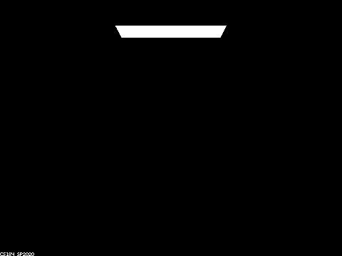
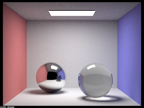
0 bounce: only self-emissive materials can be seen |
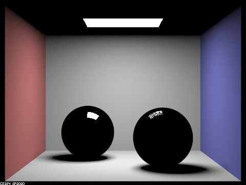
1 bounce: we start to see the direct illumination from the light on all the surfaces, including the highlights on the glass and mirror spheres |
 |
 |
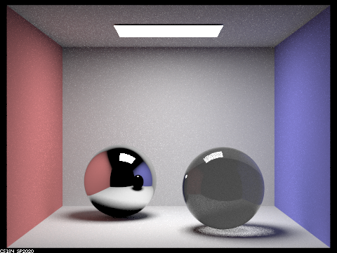
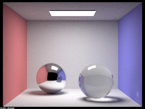
2 bounces: The mirror ball starts to reflect light that's not directly from the light source (i.e. indirect illumination). The glass ball starts to either reflect or refract lights. However, the light refracted cannot yet escape the ball, so we only see the reflected part weighted with black (the fracted part). We also start to see some mixing of colors on the walls and the upper ceiling is now visible. Note: according to Piazza, the light seen under the glass ball is due to an unidentified bug in the skeleton code. |
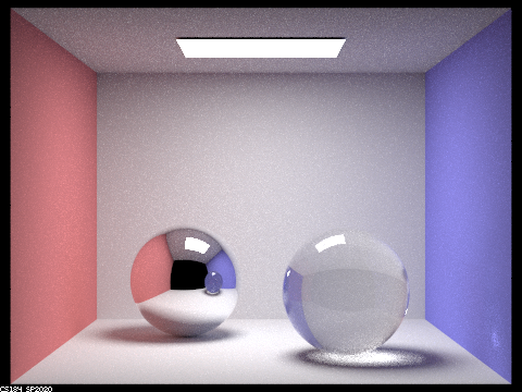
3 bounces: We see more more mixing of colors on the walls. As expected in a non-buggy verison, we also see light refracted under the glass ball. The glass ball becomes clear. The reflection seen on the mirror ball of the glass ball is similar to the glass ball seen directly in the 2 bounce-picture, because the first bounce was used on arriving at the mirror ball. |
 |
 |
4 bounces: The glass ball becomes even clearer. We start to see a white dot on the right side of the wall. This is because the light source gets first reflected from the mirror ball and then refracted within the glass ball, finally arriving at the wall. We also start to see some reflection of its own caustics on the glass ball. |
5 bounces: The glass ball becomes a bit clearer and the caustics a bit brighter; A bit less noise. |
100 bounces: not significantly different from the 5-bounces picture.
Part 2
- Show a sequence of 4 images of scene
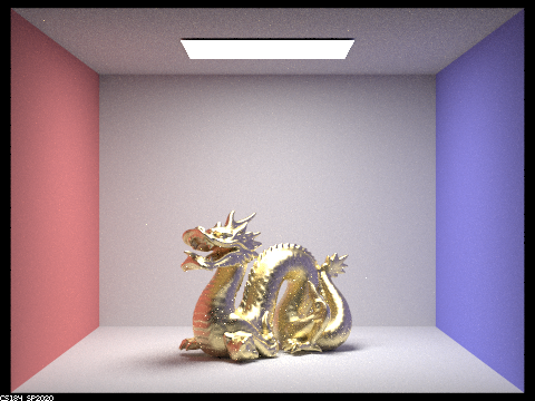
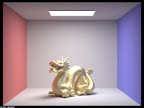
CBdragon_microfacet_au.daerendered with set to 0.005, 0.05, 0.25 and 0.5. The other settings should be at least 128 samples per pixel and 1 samples per light. The number of bounces should be at least 5. Describe the differences between different images. Note that, to change the , just open the .dae file and search for microfacet.
 |
|
|---|---|
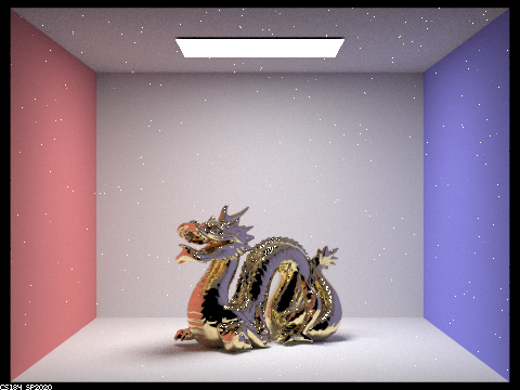
alpha = 0.005 |
alpha = 0.05 |
 |
 |
alpha = 0.25 |
alpha = 0.5 |
- Show two images of scene
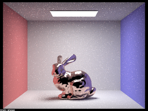
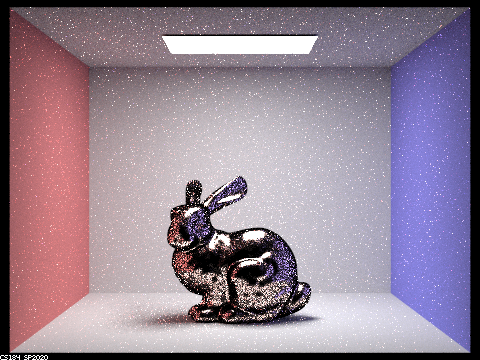
CBbunny_microfacet_cu.daerendered using cosine hemisphere sampling (default) and your importance sampling. The sampling rate should be fixed at 64 samples per pixel and 1 samples per light. The number of bounces should be at least 5. Briefly discuss their difference.
 |
 |
|---|---|
Importance Sampling |
Hemispherical Sampling |
The picture using simple hemispherical sampling is significantly noisier than the one using importance sampling because there’s a larger chance in the hemispherical sampling case to sample a direction that has a low density of microfacets.
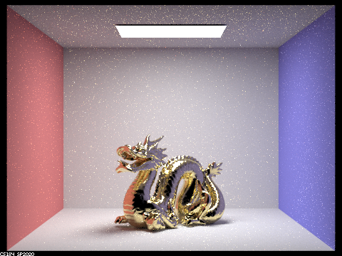
- Show at least one image with some other conductor material, replacing
etaandk. Note that you should look up values for real data rather than modifying them arbitrarily. Tell us what kind of material your parameters correspond to
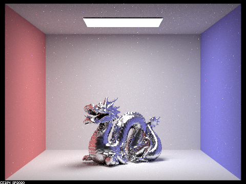
This is a mercury dragon.
Parameters:
1 | <alpha>0.1</alpha> |